| Model | FS04 | FS06 | FS08 | FS12 | FS20 | FS25 | FS40L | FS50 | FS80 |
|---|---|---|---|---|---|---|---|---|---|
| Capacity Group | Low | Medium | High | ||||||
| Normal Size ( Inch) | 1/4" | 1/4" | 3/8" | 1/2" | 3/4" | 1" | 1.5" | 2" | 3" |
| Flow Range (LPH) | 0.7 to 50 | 5 to 150 | 20 to 300 | 50 to 1200 | 150 to 2000 | 200 to 4000 | 500 to 10000 | 600 to 20000 | 1000 to 50000 |
| Accuracy | +/- 1 % of Reading +/- 0.5% of Reading (10:1 turndown) | ||||||||
| Repeatibility | Typically 0.03% of reading | ||||||||
| Temperature Range | 200C to 850 C (for Aluminium body) -200 C to 1200 C (for SS. Body) refer factory for lower and higher temperature ranges | ||||||||
| Maximum Pressure (threaded meters) in bar | |||||||||
| Aluminium Meters | 25 bar | ||||||||
| SS 316 meters | 200 bar | ||||||||
| High Pressure Model | Refer Factory | ||||||||
| Electrical for pulse meter | |||||||||
| Output | Hall Effect NPN/PNP Pulse | ||||||||
| Pulse / Liter | 5635 | 6000 | 1700 | 860 | 260 | 95 | 35 | 12 | 6 |
| Optional outputs | 4-20 mA, 485 Modbus communication | ||||||||
| physical | |||||||||
| Protection class | IP66/67 | ||||||||
| Noise generation | 75 db | ||||||||
| Dimensions | Refer datasheet | ||||||||
Oval Gear Flow Meter
Flow measuring instruments
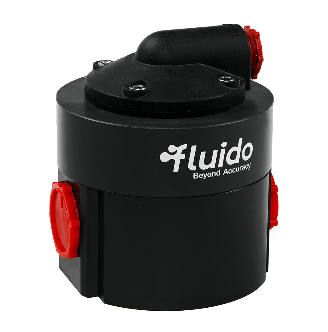
Introduction
Our Fuel Consumption System flow measuring instruments utilizes Tri-gear Flowmeters, known for their precision, reliability, and ruggedness. These advanced instruments accurately measure the volumetric flow of liquids in industrial, petroleum, and chemical applications which require high accuracy and repeatability. They operate on the Positive Displacement principle, offering a competitive alternative to Oval Gear, Sliding Vane, and Bi-Rotor options. Experience precise fuel consumption measurement and control with our cutting-edge system.
Operational Principal
Our advanced Fuel Consumption System, where the liquid flows into a single case measuring chamber, displacing two Tri gears. Each rotation of a Tri gear represents a discrete volume unit, and the gear speed directly correlates to the flow rate. Reed and Hall Effect sensors outside the pressure boundary detect Tri-gear Flowmeter movement, enabling local or remote instruments to display flow total, flow rate, or support batching applications. Meters can be fitted with additional sensors to provide in phase or out of phase signals for applications such as bidirectional flow. Experience precise and efficient fuel consumption monitoring with our cutting-edge system.
Area of Application
Oval gear flow meter (Flow Measuring Instruments) can be used for all viscous, non-abrasive clean liquids like


Petroleum Products


Oil Products


Chemicals


Grease


Fuels


Pastes

Benefits
- High Resolution Digital Output
- Digital or Analogue Outputs available
- Wide Range ability
- Less slippage
- Smoother and quieter
- Bi-directional flow capability
- Low Mass oval gears facilitate fast response
- Time to step changes in flow rate


| Model | A | B | C | D | E | F | G | H | I |
|---|---|---|---|---|---|---|---|---|---|
| FS04 | 75 | 70.88 | 11.72 | 54.19 | 10.25 | 10.25 | 45.7 | 4.25 | 4.25 |
| FS06 | 75 | 70.88 | 11.72 | 64 | 5.5 | 5.5 | 55.75 | 4.2 | 4.2 |
| FS08 | 75 | 79 | 15.2 | 64.2 | 5.5 | 5.5 | 55.75 | 4.25 | 4.25 |
| FS12 | 75 | 79 | 18.9 | 64.4 | 5.3 | 5.3 | 55.68 | 4.25 | 4.25 |
| FS20 | 88 | 91 | 24.4 | 78 | 4.7 | 4.7 | 70 | 4.25 | 4.25 |
| FS25 | 99.5 | 98 | 30.5 | 94 | 3 | 3 | 85.37 | 4.25 | 4.25 |

| Model | A | B | C | D | E | F | G | H | I |
|---|---|---|---|---|---|---|---|---|---|
| FS40 | 145 | 119 | 45 | 118.8 | 13 | 13 | 105.15 | 6.9 | 6.9 |
| FS50 | 203 | 150.9 | 56 | 167 | 18 | 18 | 153 | 6.9 | 6.9 |
| FS80 | 225 | 161 | 85 | 201.3 | 12.35 | 12.35 | 188 | 6.9 | 6.9 |
It is recommended that all "signal" cables are screened and run separately to power lines and switched inductive loads and are located well away from inverters and other "noisy" apparatus. Always use sound wiring practice. Both Hall effect and optical detectors (NPN) require a 10K Ohm external pull-up resistor connected between the output and a suitable power supply to attain a pulse. Typically the flowmeter PSU may be used but sometimes a dc pulse, which is of a different voltage, may be required e.g. using a PLC with a 24V PSU and an internal 5V rail for the pul-up
| Hall Effect Sensor | |
|---|---|
| Supply Voltage | 5-30 VDC |
| Temp. Range | 0-85 C |
| Draw Current (Max) | 20mA |

| Model with Flow Range | MOC Body | Rotor | Rotor | Thread | Output | Electrical Connection |
|---|---|---|---|---|---|---|
| FS04=1/4" + 0.7-50 | A=Alu | A=Alu | 1=NBR | 1=BSP | 1=Pulse | C=Cable |
| FS06=1/4" + 5-150 | S=S.S. | S=S.S. | 2=EPDM | 2=NPT | 2=Battery Operated Display | M=M12 Connector |
| FS08=3/8" + 20-300 | P=PPS | 3=Viton | 3=Flange | 3=Analog + Pulse | D=DIN | |
| FS12=1/2" + 50-1200 | 4=Display with analog | |||||
| FS20=3/4" + 150-2000 | 5=Display with Communication | |||||
| FS25=1" + 200-4000 | ||||||
| FS040L=1.5" + 500-10000 | ||||||
| FS50=2" + 600-20000 | ||||||
| FS80=3" + 1000-50000 |
Tri Gear Flow Meter
Flow measuring instruments
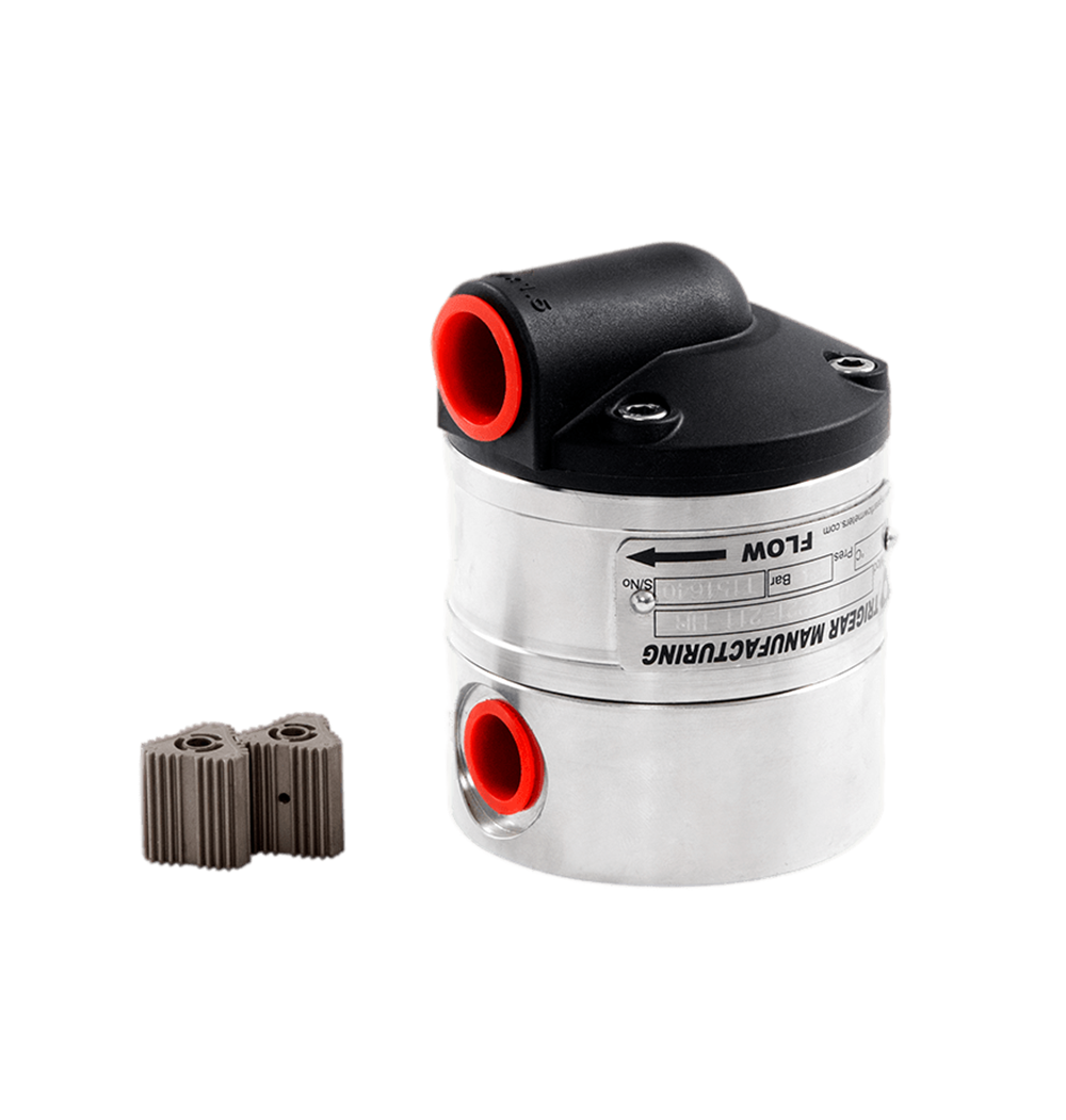
Introduction
Tri-gear Flowmeters are precise, reliable and rugged instruments for the volumetric flow of liquids in general industrial, petroleum and chemical applications that require high degrees of accuracy and repeatability. They operate on the Positive Displacement principle using advanced gear technology and offer a competitive alternative to their Oval Gear, Sliding Vane and Bi-Rotor alternatives.
Operational Principal
Liquid Passes into the single case measuring chamber and displaces two Trigears. Each rotation of a Tri-gear Flowmeters is proportional to a discrete unit of volume, in turn, the speed at which the gears rotate is directly proportional to flowrate. Reed and Hall Effect sensors mounted outside the pressure boundary detect the movement of the Tri-gears, thus allowing local or remote instruments to display flow total, rate of flow or facilitate batching applications. Meters can be fitted with additional sensors to provide in phase or out of phase signals for applications such as bidirectional flow.
Benefits
- High Resolution Digital Output
- Wide Rangeability
- Bi-directional flow capability
- HART Output option
- Less slippage than oval gear meters.
- Smoother and quieter than Oval Gear Meters.
- Dual Output standard (reed and hall effect)
- Low Mass Tri-gears facilitate fast response time to step changes in flowrate.
| Model Prefix | TG008 | TG015 | TG020 | TG025 | TG040 | TG050 |
|---|---|---|---|---|---|---|
| Capacity Group | Small Capacity | Medium Capacity | ||||
| Nominal size (inches) | 8mm (3/8”) | 15mm (1/2”) | 20mm (3/4”) | 25mm (1”) | 40mm (1.5”) | 50mm (2”) |
| *Flow range – litres/min – US gal/min |
0.25 ~ 9.2 | 1-40 | 2 ~ 50 | 5 ~ 150 | 10 ~ 250 | 20 ~ 500 |
| 0.07 ~ 2.4 | 0.3 ~ 10.5 | 0.6 ~ 13 | 1.3 ~ 40 | 2.6 ~ 66 | 5 ~ 132 | |
| **Accuracy @ 3cp | ± 0.5% of reading | ± 0.25% of reading (15:1 turndown), ± 0.5% of reading (25:1 turndown) |
||||
| Repeatability | typically ± 0.01% of reading | |||||
| Temperature range | -20°C ~ +120°C (-4°F ~ +250°F), refer factory for lower & higher temperatures | |||||
| Maximum pressure (threaded meters) bar (PSI) | ||||||
| Aluminium Meters | 30 (440) | |||||
| 316 Stainless Steel meters | 34 (495) | 30 (440) | ||||
| High Pressure models | refer factory | |||||
| Electrical – for pulse meters (see below for optional outputs) | ||||||
| Output pulse resolution | Pulses/litre (pulses/US gallon) – nominal | |||||
| Reed Switch and Hall Effect | 670 (2546) |
77 (292.6) |
77 (292.6) |
33.5 (125.4) |
11.5 (43.7) |
6.5 (24.7) |
| High Resolution Hall / Quadrature | 1340 (5092) |
154 (585.2) |
154 (585.2) |
67 (254.6) |
23 (87.4) |
13 (49.4) |
| Reed Switch output | 30Vdc x 200mA max. (maximum thermal shock 10°C (50°F)/minute) | |||||
| Hall Effect output (NPN) | 3 wire open collector, 5 ~ 24Vdc max., 20mA max. | |||||
| Optional outputs | 4 ~ 20mA, scaled pulse, quadrature pulse, flow alarms or two stage batch control | |||||
| Physical | ||||||
| Protection class | IP66/67 (NEMA4X), integral ancillaries can be supplied Intrinsically Safe | |||||
| Noise generation @ maximum flow | - | 75db | ||||
| Dimensions | Refer datasheet | |||||
| Pressure drop chart | Refer datasheet | |||||
| Min. filtration – microns (mesh) | 75 microns (200 mesh) |
150 microns (100 mesh) | ||||
| Approximate shipping weights (basic threaded meter) kg | ||||||
| Stainless Steel | 2.2 | 3.0 | 3.0 | 4.0 | 9.0 | 12.0 |
| Aluminium | 1.0 | 1.5 | 1.5 | 2.0 | 4.0 | 6.0 |

